
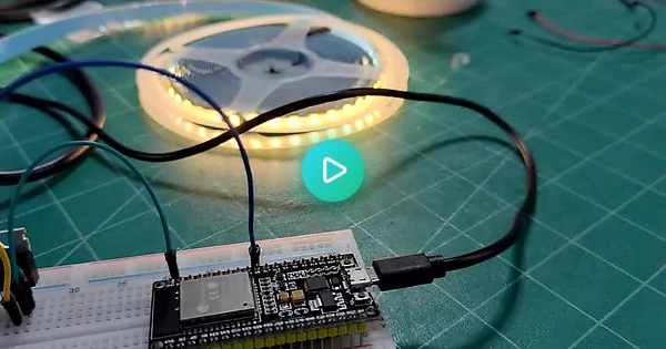
My project is a “breathing” white 12v LED strip controlled by an esp32 on a dev board, and switched with an IFLZ44N mosfet.
In my video you can see it working but also hear the power supply complaining.
I’m using the LEDC Arduino library which allows me to select the frequency and resolution for PWM.
If I set the frequency too low the whine is extreme, but at this setting it’s the best I’ve been able to achieve, which is about 9000Hz. Unfortunately you can still hear the sound from across the room!
It is a cheapo solid state power supply that claims it can output 12v up to 25A. I tried my desktop supply and it emits some whine too, so I don’t think replacing the power will totally fix this.
Is there a technique for tuning the frequency or even just masking it somehow?
Caps are definitely the first thing to try. To add on, the higher your frequency, the smaller caps you’ll need. At 10kHz you’ll need around 200uF of decoupling but at 50kHz you’d only need around 40uF. The smaller capacitance means you can find caps with better ESR, or just fit into a smaller space in general.
The drawback of higher frequency is that you’ll be charging and discharging the gate of the MOSFET more often, which could mean heating it up and hitting thermal limits quicker. There’s also a tradeoff within the MOSFET itself between low on-resistance and lower required gate charge - for slow switching you can find a FET with low Rds and high gate charge since youd be switching less often, but for very high frequency applications the amount of energy you put into charging and discharging the FET (mostly since the FET will spend a longer time in its linear region) can outweigh the savings of the lower resistance. Yay tradeoffs!
Thanks for typing this up! This helps me understand a lot more about what is going on.
I may have purchased too large of cap for the first try: 470uF. I bought it online so still waiting for arrival. I’ll get some in the 40uF to 200uF range for more testing
470uf should be fine - bigger is almost always better, except if you sacrifice higher ESR for it in an application that requires lower ESR. It’s pretty common to combine a large cap with higher ESR (like an Electrolytic or tantalum) with low ESR ceramic caps. That way the large cap can handle the high speed bulk C while the smaller cap can handle the high speed stuff and switching edges.
Did you make sure the cap you picked out was rated for the voltage you are working with? For hobbyist stuff it’s usually a good idea to heavily derate voltages, to avoid blowing things up. For example, if I was working with a 24V power supply, I wouldn’t nab a 25V cap; I would spring for a 35V (or even a 50V if I’m feeling particularly paranoid). You’ll see derating like this commonly in commercial applications, and extremely frequently in military/aerospace applications.
As a rule of thumb you should always derate by at least 20%, then increase to 100% depending on how much ripple or switching the cap will see. For this application I’d probably want to derate to at least 50%